26 questions from 2021
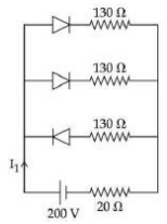
In the given figure, each diode has a forward bias resistance of \( 30 \, \Omega \) and infinite resistance in reverse bias. The current \( I_{1} \) will be:
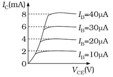
The typical output characteristics curve for a transistor working in the common-emitter configuration is shown in the figure. The estimated current gain from the figure is:
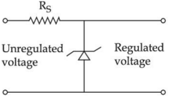
A zener diode of power rating \( 2 \, \text{W} \) is to be used as voltage regulator. If the zener diode has a breakdown of \( 10 \, \text{V} \) and it has to regular voltage fluctuated between \( 6 \, \text{V} \) and \( 14 \, \text{V} \), the value of \( R_{S} \) for safe operation should be _______ \( \Omega \).
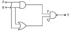
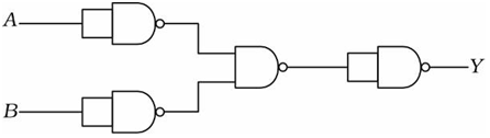
The logic circuit shown above is equivalent to:
Zener breakdown occurs in a \( p \)-\( n \) junction having \( p \) and \( n \) both:
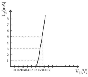
For the forward biased diode characteristics shown in the figure, the dynamic resistance at \( I_D = 3 \, \text{mA} \) will be \( \_\_\_\_\_\_ \, \Omega \).
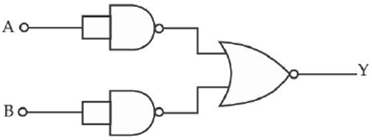
The output of the given combination gates represents:
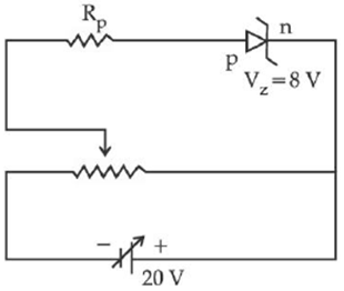
A zener diode having zener voltage \( 8 \, \text{V} \) and power dissipation rating of \( 0.5 \, \text{W} \) is connected across a potential divider arranged with maximum potential drop across zener diode is as shown in the diagram. The value of protective resistance \( R_P \) is ________ \( \Omega \).
Statement I :To get a steady dc output from the pulsating voltage received from a full wave rectifier we can connect a capacitor across the output parallel to the load \( R_L \).Statement II :To get a steady dc output from the pulsating voltage received from a full wave rectifier we can connect an inductor in series with \( R_L \).In the light of the above statements, choose the most appropriate answer from the options given below:
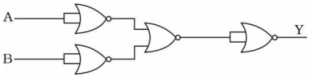
Four NOR gates are connected as shown in figure. The truth table for the given figure is:
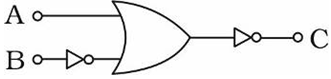
The following logic gate is equivalent to:
Identify the logic operation carried out.
For a transistor in CE mode to be used as an amplifier, it must be operated in:
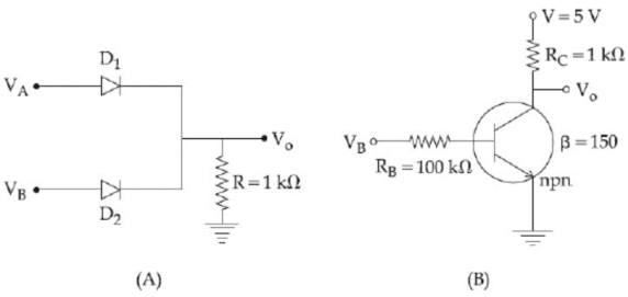
If \( V_{A} \) and \( V_{B} \) are the input voltages (either \( 5 \, \text{V} \) or \( 0 \, \text{V} \)) and \( V_{0} \) is the output voltage then the two gates represented in the following circuits (A) and (B) are:
Given below are two statements:Statement : I PN junction diodes can be used to function as transistor, simply by connecting two diodes, back to back, which acts as the base terminalStatement : II In the study of transistor, the amplification factor \(\beta\) indicates ratio of collector current to the base currentIn the light of the above statements, choose the correct answer from the options given below:
For a transistor \( \alpha \) and \( \beta \) are given as \( \alpha = \dfrac{I_C}{I_E} \) and \( \beta = \dfrac{I_C}{I_B} \). Then the correct relation between \( \alpha \) and \( \beta \) will be:
A circuit is arranged as shown in figure. The output voltage \( V_0 \) is equal to ______ V.
In the following logic circuit the sequence of the inputs A, B are \( (0, 0) \), \( (0, 1) \), \( (1, 0) \) and \( (1, 1) \). The output \( y \) for this sequence will be:
The correct relation between \( \alpha \) (ratio of collector current to emitter current) and \( \beta \) (ratio of collector current to base current) of a transistor is:
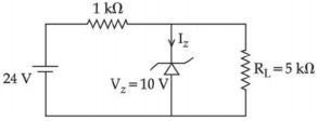
For the given circuit, the power across zener diode is __________ mW.
A transistor is connected in common emitter circuit configuration, the collector supply voltage is \( 10 \, \text{V} \) and the voltage drop across a resistor of \( 1000 \, \Omega \) in the collector circuit is \( 0.6 \, \text{V} \). If the current gain factor \(( \beta) \) is \( 24 \), then the base current is _______ \( \mu \text{A} \). (Round off to the Nearest Integer)
In a semiconductor, the number density of intrinsic charge carriers at \( 27^\circ \text{C} \) is \( 1.5 \times 10^{16} \, /\text{m}^{3} \). If the semiconductor is doped with impurity atom, the hole density increases to \( 4.5 \times 10^{22} \, /\text{m}^{3} \). The electron density in the doped semiconductor is ______ \( \times 10^{9} \, /\text{m}^{3} \).
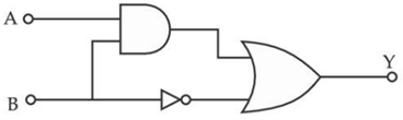
Find the truth table for the function \( Y \) of \( A \) and \( B \) represented in the following figure.
An npn transistor operates as a common emitter amplifier with a power gain of \( 10^{6} \). The input circuit resistance is \( 100 \, \Omega \) and the output load resistance is \( 10 \, \text{k}\Omega \). The common emitter current gain \( \beta \) will be ______________. (Round off to the Nearest integer)
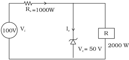
For the circuit shown below, calculate the value of \( I_z \):
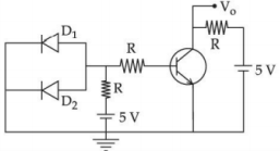
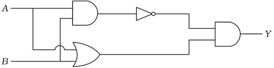
Which one of the following will be the output of the given circuit?